01
Before core cutting
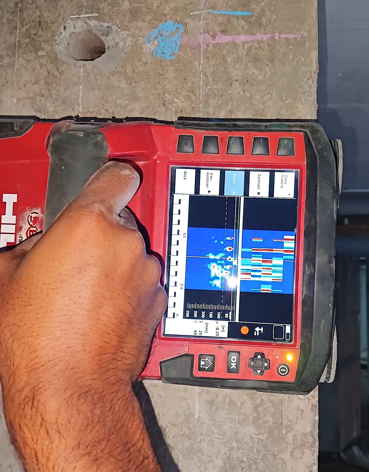
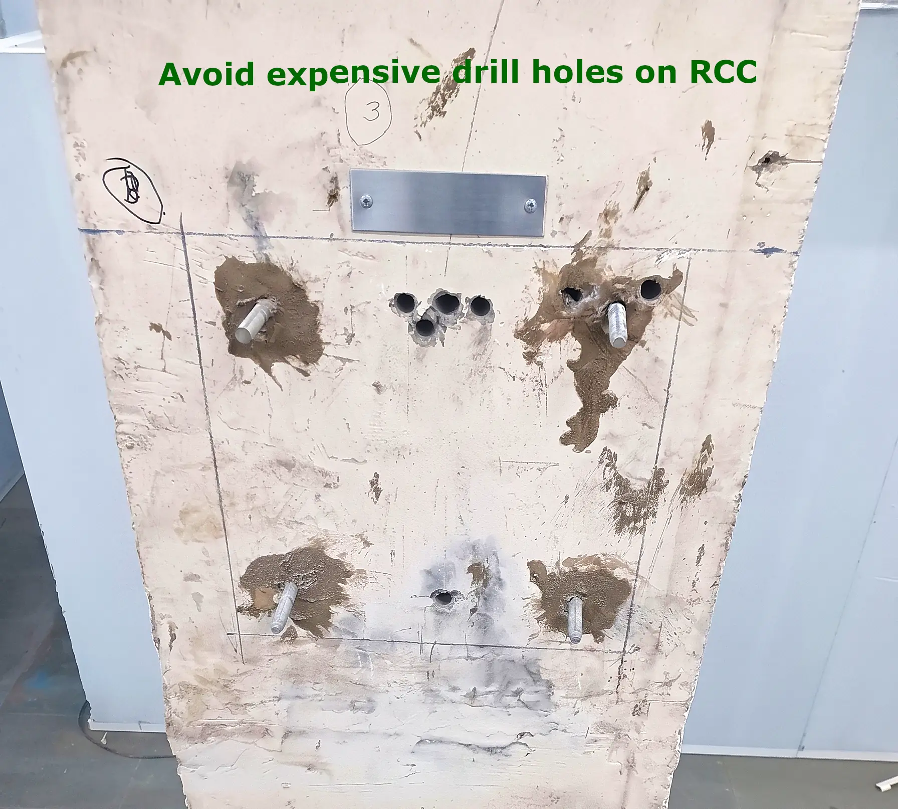
Find the reinforcement before the cutter does. Bars and ducts located, clear windows identified, permissible diameter stated at each proposed core position.
GPR CONCRETE SCANNING / REBAR / PT CABLES / AHMEDABAD, MUMBAI, PAN-INDIA
Scanforte locates reinforcement, post-tensioning tendons, conduits, voids and delamination inside RCC using ground penetrating radar, so your team can core, drill and certify on evidence instead of on drawings. HILTI PS 1000 X-Scan hardware, expert mode acquisition, and interpretation by a structural engineer. Results marked on the element the same visit.
From ₹15,000/day and or project-based
SCANNED FOR TEAMS AT — IN ORDER OF ENGAGEMENT































SCAN OUTPUT AND SITE WORK, AS IT HAPPENS
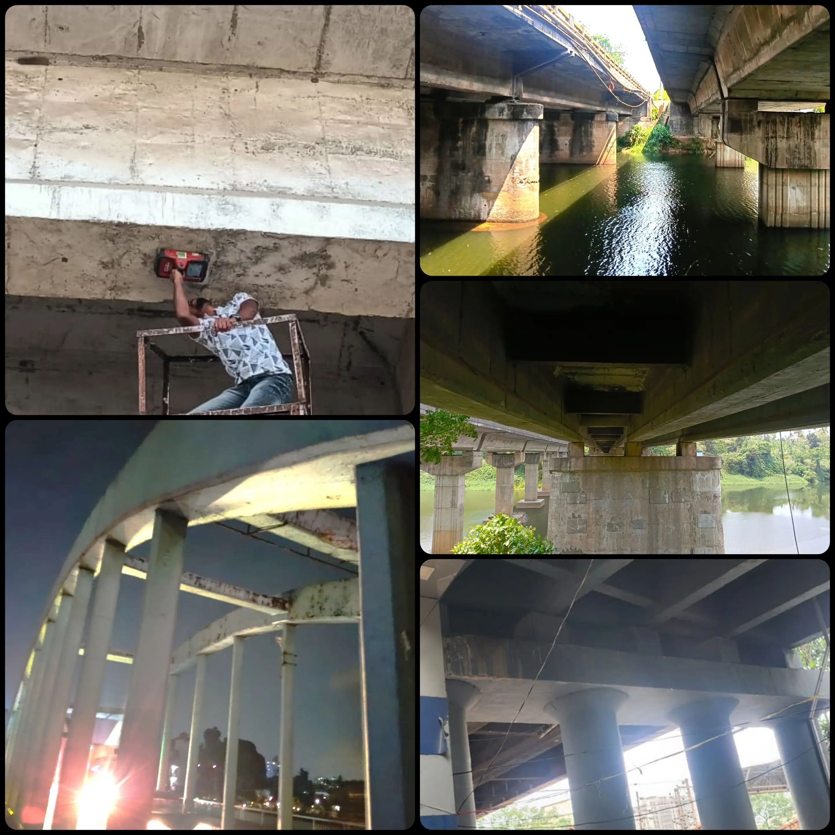
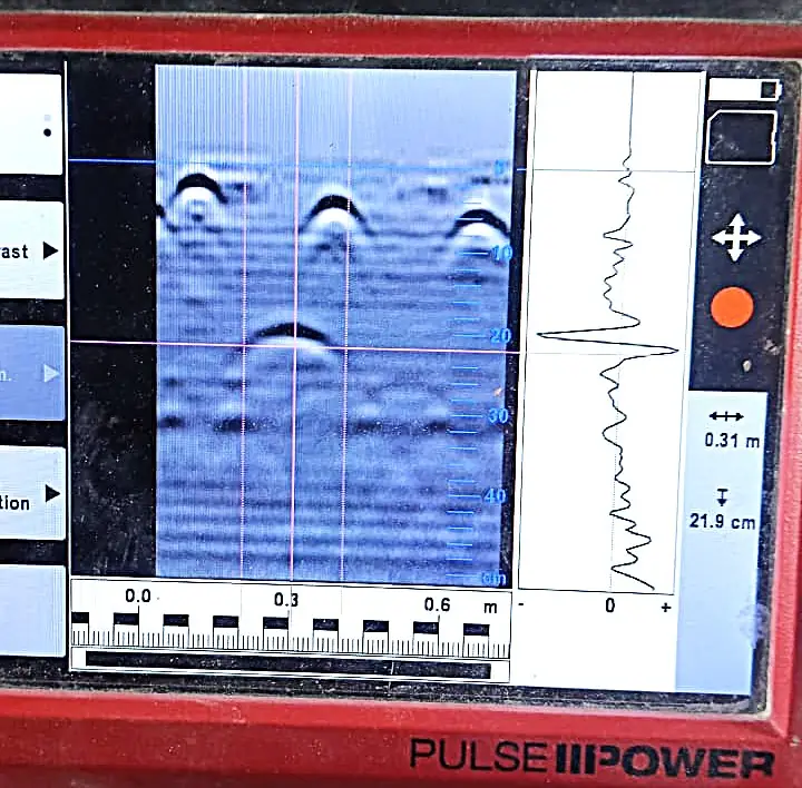
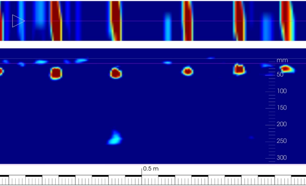
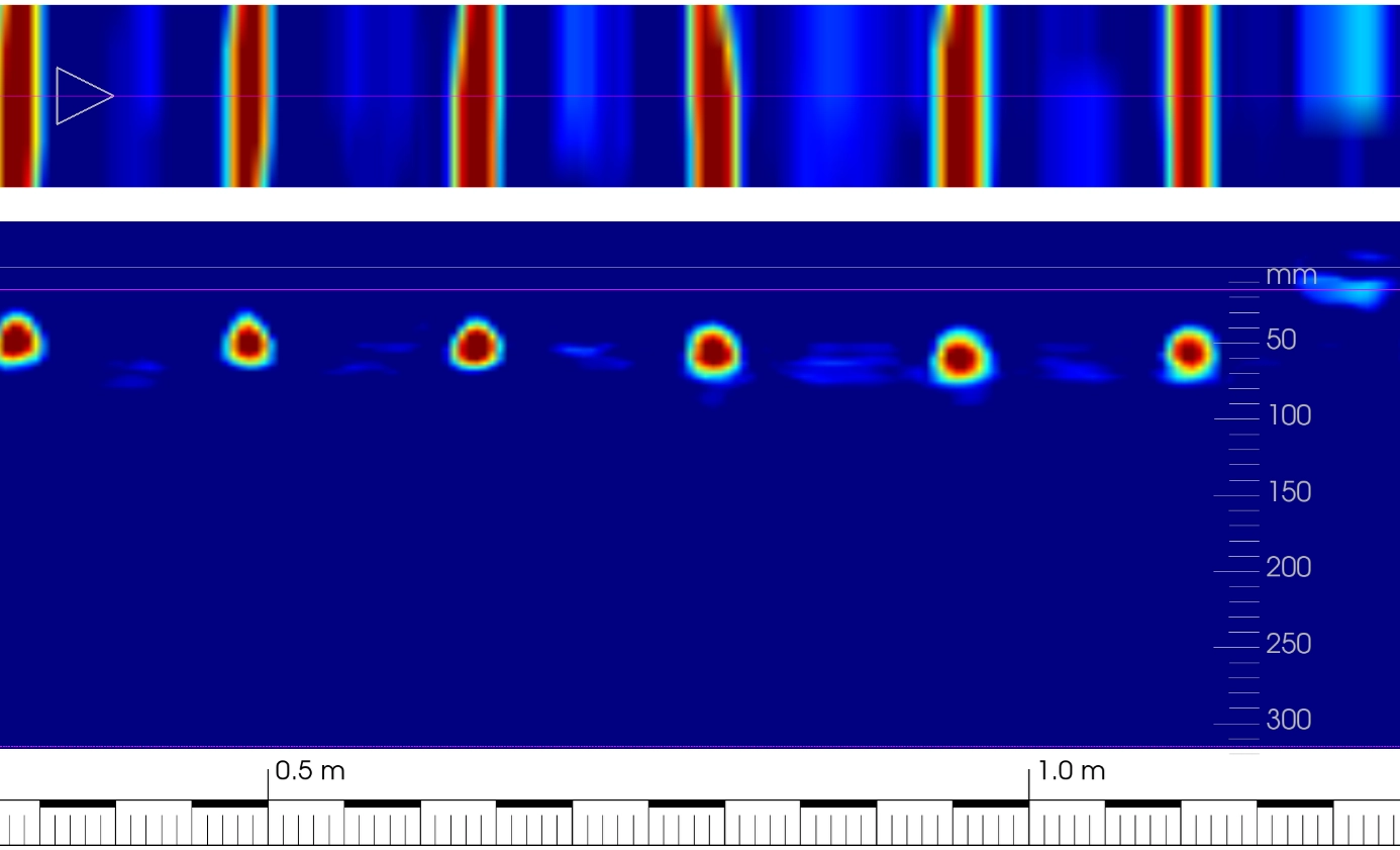
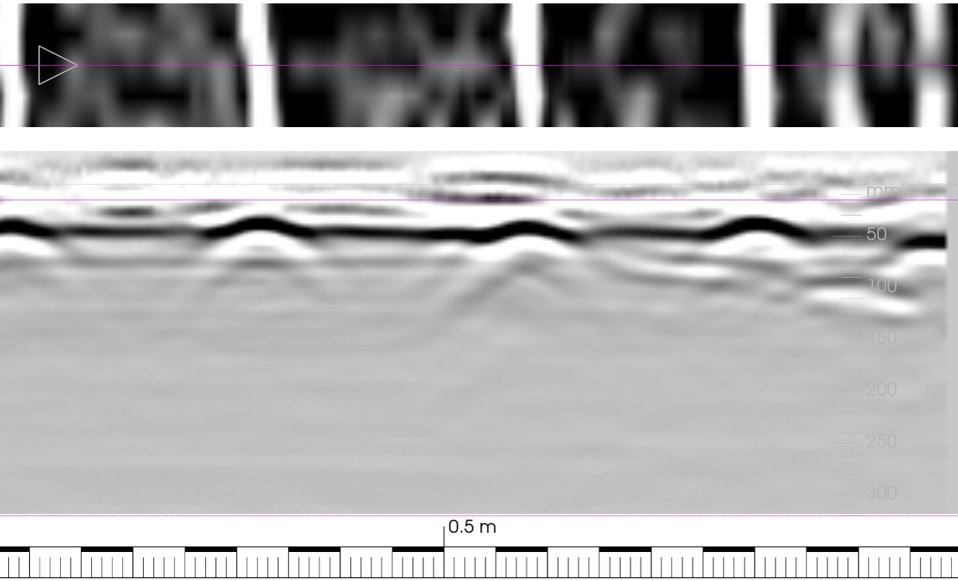
Continuous GPR practice, first as Dbond Structural Solutions, since 2024 as Scanforte.
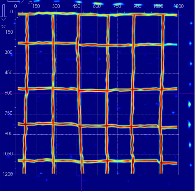
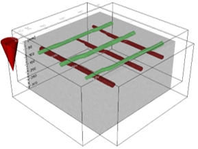
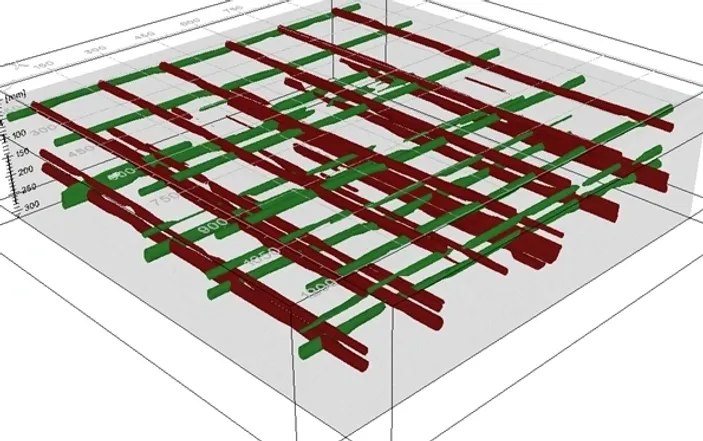
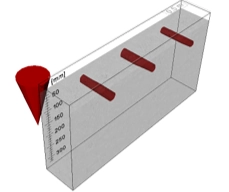
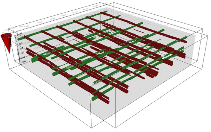
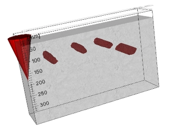
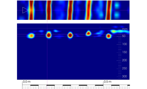
Three antenna X-Scan imaging in plan view, section view, and multi-layer probe.
Laboratory practice aligned to ISO 17025:2017 and ISO 9001:2015 quality management.
As built reinforcement moves. Ducts sag between supports. Conduits are added during service and never recorded. A drilled hole that severs a main bar becomes a structural repair, and a core through a stressed tendon becomes an incident.
Ground penetrating radar answers the question the drawing cannot: what is actually in this element, at what depth, at this exact position, today. The scan is only worth commissioning if it answers the next site decision, so that is where we start.
01
Find the reinforcement before the cutter does. Bars and ducts located, clear windows identified, permissible diameter stated at each proposed core position.
02
Rebar, PT tendons, conduits and embedded services located before an anchor goes in, on renovation, fit out and strengthening work.
03
Voids, delamination and moisture affected zones turned from scattered bright spots into plan extents you can mark up, price and act on.
Every survey is specified against a site decision: where to cut, whether to certify, what to repair, and how much of it.
The scan that prevents the expensive mistake. Post-tensioning ducts, tendon profiles, anchorage zones and main reinforcement located and marked on the live structure before coring, cutting or opening. For each proposed position we state the permissible core diameter and the depths of the reinforcement layers around it.
Marked on the element, same visit. Grid acquisition in two orthogonal directions, so every bar is confirmed twice.
Bar location, spacing, orientation and concrete cover in plan view, layer by layer, checked against the nominal cover of IS 456:2000 clause 26.4. Depths are calibrated on your element, not read off a default setting.
The complete X-Scan platform on your site for the duration of the works, with an experienced scanning operator. Project based terms.
Grout voids inside PT ducts, honeycombing behind congested steel, and delamination at the reinforcement level, mapped as plan extents rather than isolated bright spots.
Electrical conduits, PVC and metallic services, and other embedded objects located inside slabs and walls before fit out, alteration or demolition.
Submerged, tidal and splash zone elements, chloride contaminated concrete and heavily congested reinforcement are exactly where most GPR surveys fail outright. It is genuinely difficult radar, and we say so upfront rather than after the invoice. What we can tell you at enquiry stage is whether a usable result is realistic on your element, calibrated per exposure zone rather than per structure, before anyone commissions the work.
Reinforcement layouts, moisture extents and corrosion extents on decks, piers, jetties and industrial structures, recorded before strengthening design is fixed.
Full core cutting location survey page →
Cutting contractors cut. They cannot tell you a position is clear of reinforcement and post-tensioning: that assurance is what we supply, and only that, marked directly on the element before anyone mobilises a rig.
On post-tensioned slabs it isn't a precaution. A severed tendon releases stored energy and turns a routine opening into a structural investigation.
Full HILTI PS 1000 rental page →
The PS 1000 is a three antenna ground penetrating radar system that produces plan view images of concrete, not the single line trace of a covermeter or a rebar scanner. It records a 600 by 600 mm image scan grid in a single set up, extendable to 1200 mm by 1200 mm for larger elements, and detects to a stated maximum of 300 mm in concrete.
The instrument is a necessary condition, not a sufficient one. Default settings assume dry, ordinary concrete, and most structures that need scanning are neither. We acquire in expert mode with the phase of the signal preserved, calibrate the dielectric constant on the element in front of us, and process in PROFIS Detection together with our own MATLAB routines. Amplitude alone tells you something is there. Polarity, arrival time and attenuation tell you what it is.
The complete HILTI PS 1000 X-Scan platform is available on project based rental, with an experienced scanning operator, subject to availability and site conditions.
Before you rent, one point worth stating plainly. The hardware is the smaller half of the result. On dry, lightly reinforced concrete a competent site engineer will get usable data from the default settings. On wet, saline, congested or unusual concrete, which is where most scanning requirements arise, the outcome is decided by calibration and interpretation rather than by the instrument. For those elements an operated survey usually costs less than a rental that has to be repeated.
Check rental availabilityDetection depth is application dependent. Achieved depth of investigation varies with concrete composition, moisture content, chloride content, reinforcement congestion and target size, and is stated explicitly in every report we issue.
Each one takes about a minute to read. Equipment: HILTI PS 1000 X-Scan. Processing: PROFIS Detection in expert mode with our own MATLAB routines. Client names and locations are withheld. Site photographs and raw data are on file.
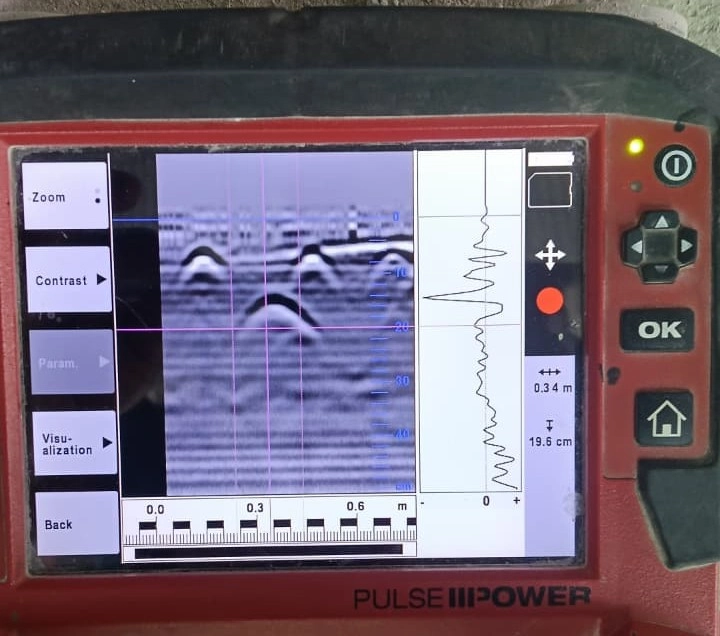
The problem. The slab was cast, stressed and grouted, and the grouting inside the post-tensioning ducts could not be verified. Handover was held up. An ungrouted length leaves prestressing strand without bond and without alkaline protection.
Why it was hard. The duct is the brightest reflector in the slab, so its inside sits in its own shadow. A void is not a new object. It is missing grout in a space the strongest echo already occupies. Brightness alone cannot separate the two, and automatic detection marks the duct either way.
What we did. We read the sign of the reflection instead of its brightness. Grout and water invert the wavelet. Air does not. Working in expert mode with the phase kept intact, on a registered grid along each tendon, an air filled length showed a reversed polarity echo at the duct crown, ringing repeats, and reflectors below pulled upward because the pulse crosses air faster.
Result. Void zones marked on the slab with their extent along each duct, in time for the client handover date, with no exploratory breaking of a stressed slab.
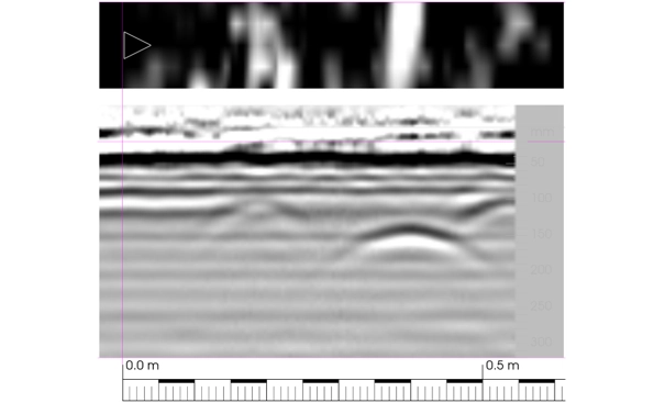
The problem. Cores were needed through structural elements. Standard scanning had already been tried and produced nothing the client engineers were prepared to cut on. A wrong call meant a severed main bar and a structural repair.
Why it was hard. The concrete used a fine aggregate of non standard mineralogy. That changes the electromagnetic behaviour of the mix, not its strength: higher attenuation, slower pulse, and far more scatter off the matrix itself. Aggregate returns competed with bar returns, so the image had no usable contrast.
What we did. Recalibrated the dielectric constant on this mix using a bar of known cover, then reacquired in grid mode so every bar was confirmed in two directions. Processing used our own parameter set for noisy matrices: narrowed filter band, background removal, and gain fitted to the measured attenuation rather than a default ramp. Reinforcement then resolved layer by layer in plan view.
Result. Bars marked with depths, core positions set out in the clear windows between them, permissible core diameter stated at each. No reinforcement cut.
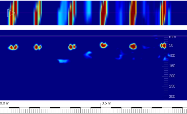
The problem. A retrofitting programme covering 28 bridges in one state needed reinforcement layouts, moisture extents and corrosion extents before design could be fixed. The substructures were in continuous contact with water, and conventional scanning had not returned usable data on them.
Why it was hard. Water attacks radar from both sides. Its dielectric constant is about 81 against 6 for dry concrete, so the pulse slows and every depth reads wrong. The ionic pore solution also raises conductivity, so the signal is absorbed and the lower half of the record goes blank. Taken at face value that reads as a clean pier. It is the opposite.
What we did. Treated the signal loss as the measurement. Calibration was carried out separately for submerged, splash and dry bands on the same element, gain was fitted to the attenuation actually measured, and the datasets were mapped in MATLAB three ways: attenuation, arrival time shift, and reflection polarity. Together those separate moisture ingress from delamination from section loss at the bar, readings that a single radargram confuses.
Result. All 28 structures surveyed and reported in one comparable format, each with its achieved depth of investigation stated, so the owner could rank intervention across the network.
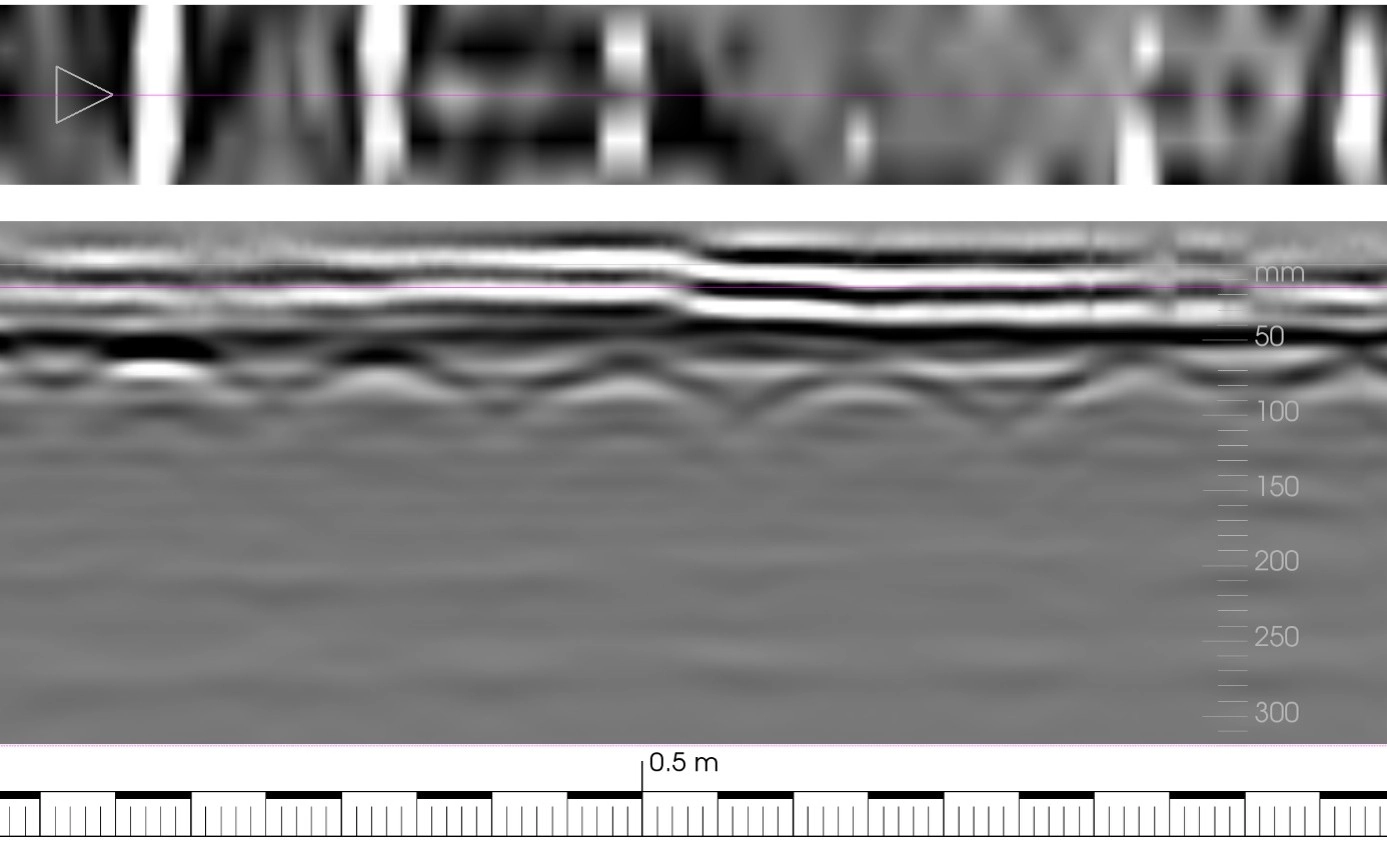
The problem. Part of a slab in one room had collapsed. We were called to inspect the remaining rooms, slabs and elements and establish whether the same conditions existed elsewhere. The client needed to know which areas to release, which to prop, and where repair had to start.
Why it was hard. The building was occupied and partly distressed, so nothing invasive was possible, and the answer was needed quickly. Moisture varied room to room, which shifts the depth reading if a single calibration is used across the floor.
What we did. Gridded the elements from the soffit and, where reachable, the top surface, calibrating each element separately. Delamination gives a three part signature that can be looked for directly: a flat echo with air type polarity, ringing repeats at even intervals, and loss of the bar response beneath it. Depth slices at and just below the reinforcement level showed those zones as continuous areas in plan rather than scattered bright spots.
Result. Delaminated zones and reinforcement irregularities mapped with plan extents and depths, letting the client rectify promptly. The report was explicit about what radar does not answer: cause of collapse and residual capacity require ultrasonic pulse velocity, impact echo and a small number of agreed cores.
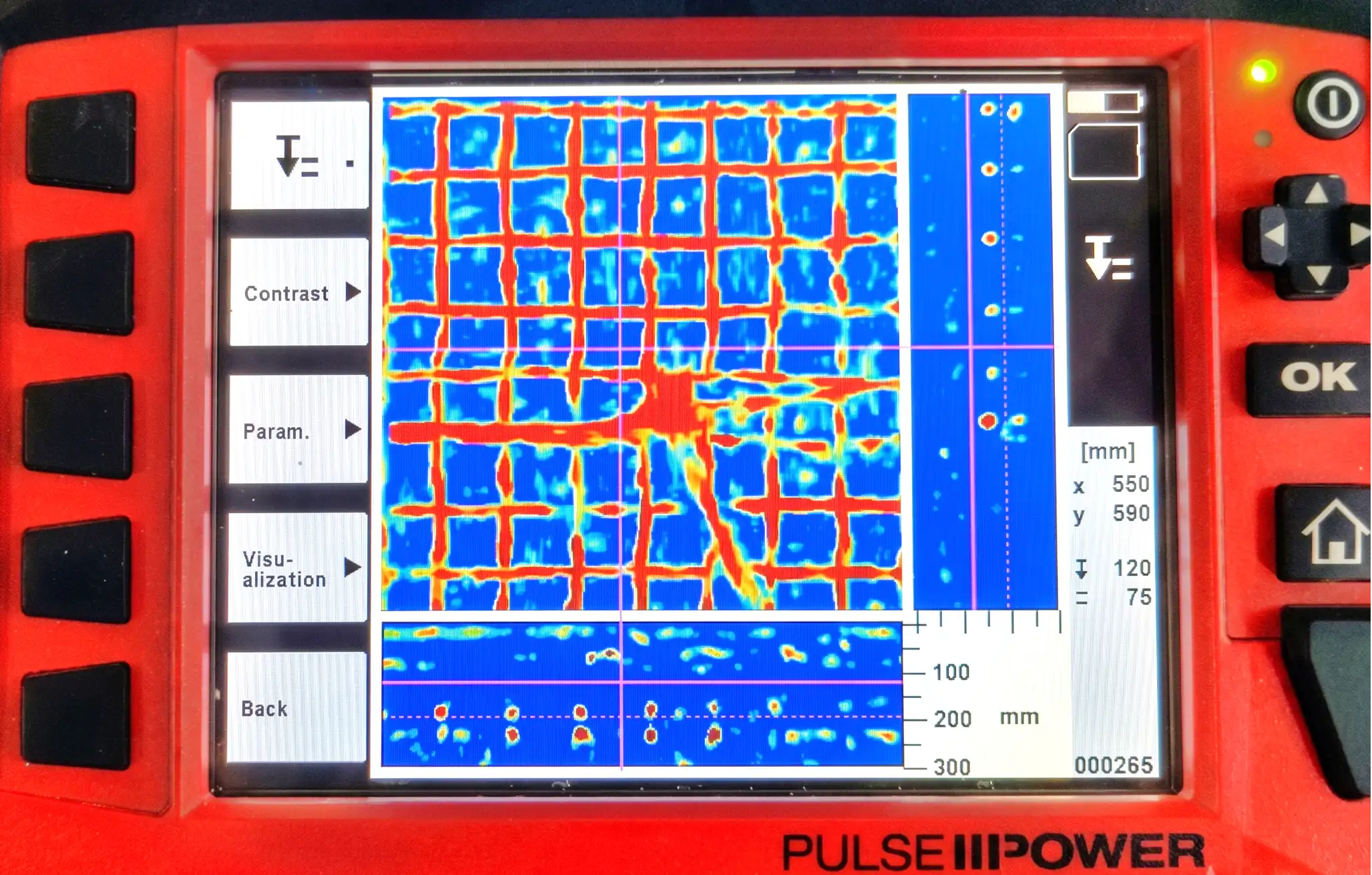
The problem. The client needed the extent of reinforcement corrosion in an RCC jetty in continuous contact with saline water, across submerged, tidal, splash and atmospheric zones.
Why it was hard. This is the worst case for radar. Chloride in the pore solution drives conductivity up and absorbs the pulse. High free water content drives the dielectric constant up and displaces every depth reading. Both change with height above water on the same pile. A standard set up closes the detection window above the reinforcement exactly where deterioration is worst.
What we did. Expert mode from the outset, with parameters derived per exposure zone rather than per structure, filters set to keep the low end of the band that survives in conductive concrete, and phase preserved. Our MATLAB routines then classified each element face into three separate conditions: corroding bars, shown by localised loss and broadening along the bar line, delamination, shown by a flat air type reflector with repeats, and disintegrated concrete, shown by incoherent high scatter zones with no ordered bar pattern at all.
Result. The three conditions mapped separately, so repair could be specified proportionately, whether patch repair, cover replacement or reconstruction, instead of applying the costliest remedy everywhere. Chloride profiling and half cell potential testing to ASTM C876 were recommended at a small number of agreed locations for quantitative confirmation.
These are records of specific investigations, not a statement that every element will produce the same result. What radar resolves on any given structure depends on its moisture content, chloride content, reinforcement congestion and mix. We assess that at enquiry stage and say so before the survey is commissioned.
If a scan on your project has come back inconclusive, send us the element details, the exposure condition and the output you already have.
Send us an inconclusive scan01
Air is 1 and passes the pulse at 300 mm per nanosecond. Dry concrete is 5 to 8, saturated concrete 10 to 20, water about 81. Steel returns the pulse instead of passing it.
v = c / √εr02
Here t is the two way travel time. Every stated depth therefore carries the error in the assumed permittivity. Calibrate on the element, on a bar of known cover.
d = v · t / 203
Water, grout and steel invert the reflected wavelet. Air does not. That sign is what separates a filled anomaly from an empty one, and it is discarded by amplitude only displays.
04
Conductivity, not permittivity, decides whether a target appears at all. Mapped as a lateral gradient, that signal loss becomes the boundary of the affected zone rather than a gap in the data.
05
Where bar pitch falls below the antenna footprint, echoes merge into one band and starve everything below it. The remedy is geometric: orthogonal grids and plan view slices, not more power.
06
GPR does not measure chloride content, compressive strength, corrosion rate or residual capacity. For those we name the test: half cell potential to ASTM C876, resistivity, ultrasonic pulse velocity, impact echo, or a small number of agreed cores.
01
Send the element type, thickness, exposure condition and what you need to locate on WhatsApp. Photographs, drawings and any previous scan output help us assess it fast.
02
We check access, moisture, exposure and reinforcement congestion against your target, confirm radar is the right test, and schedule the visit.
03
Calibrated on the element, scanned in an orthogonal grid, and marked directly on the surface for your coring or cutting crew, same visit.
04
Depth slices, plan extents and permissible core diameters, issued as a written report when your project requires formal documentation.
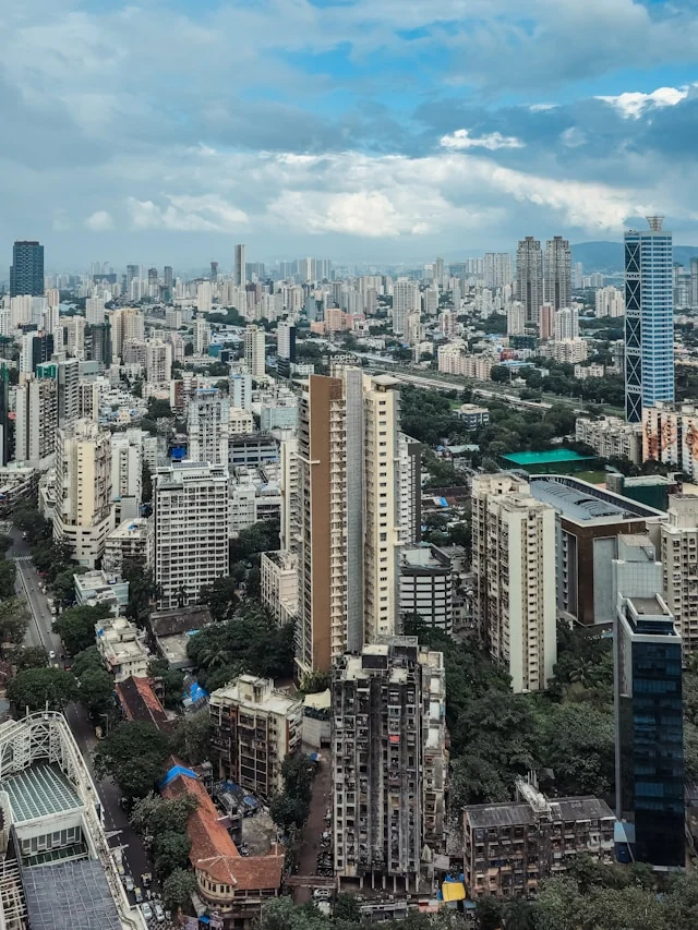
Slabs, beams, columns and walls. Coring and drilling preparation, fit out alterations, and investigation of existing construction where no reliable drawing survives.
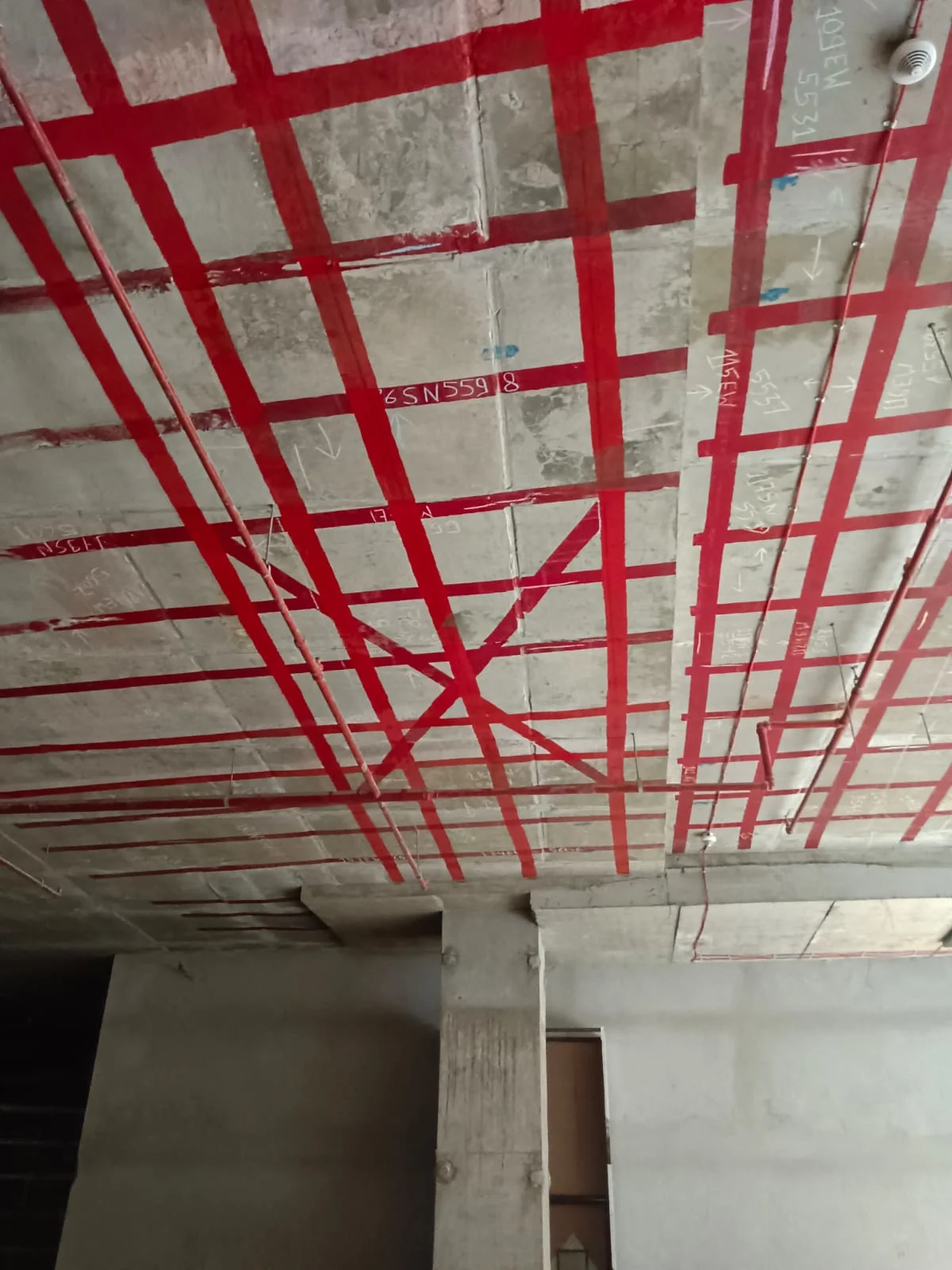
Tendon profiles, duct locations, anchorage zones and grouting verification, before any opening is formed in a stressed slab.
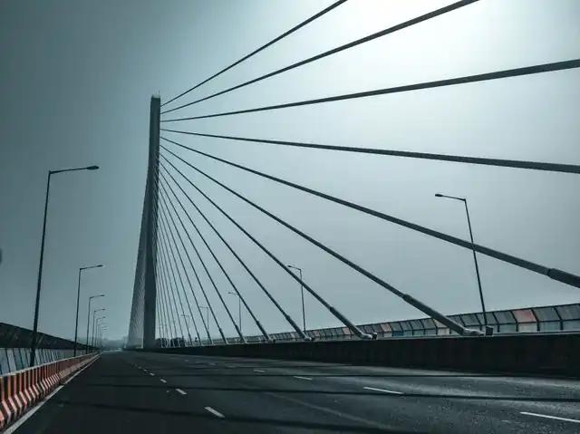
Deck reinforcement, pier and abutment condition, moisture and corrosion extents, recorded across a network in one comparable format.
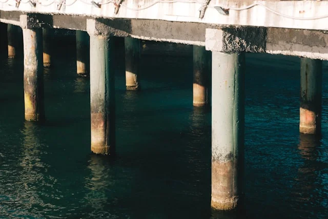
Jetties, berthing structures and piles under continuous saline exposure, with parameters derived separately for submerged, tidal, splash and atmospheric zones.

Foundations, machine bases, industrial slabs and embedded services, surveyed without interrupting operations.

Non-destructive documentation where nothing invasive is permitted, and rapid assessment where a structure is occupied or partly damaged.
Scanforte provides GPR concrete scanning services across India, from bases in Ahmedabad and Thane. Site mobilisation runs out of Mumbai and Thane, not Ahmedabad, for faster attendance across the Mumbai Metropolitan Region and western India. Mobilisation to remote, offshore and island locations is quoted per project.
Check availability for your locationBase for site mobilisation. Same day or next day attendance across the Mumbai Metropolitan Region and Pune, covering post-tensioned floor plates, occupied building surveys and coastal exposure work. Pune also has its own dedicated coverage page.
Registered base and coverage of the Gujarat industrial belt, on scheduled visits.
Covered from Ahmedabad on scheduled visits, with multiple sites combined into one mobilisation where possible.
Project based mobilisation, typically for multi element surveys and infrastructure programmes.
Bridge networks, marine structures and industrial assets anywhere in the country, priced per programme.
WHO WE WORK FOR
Structural consultants and forensic engineers. Retrofitting and rehabilitation contractors. Testing laboratories and third party inspection agencies. Asset owners, developers and public infrastructure authorities.
Every survey is interpreted personally by Bhargav Shobhana, assistant professor of structural engineering, working in earthquake engineering and ground penetrating radar. There is no sales layer between the person who takes your enquiry and the person who reads your data: the engineer who calibrates the element is the engineer who reads the record.
The practice began in 2019 as Dbond Structural Solutions and has operated as Scanforte Concrete Analytics since 2024, dedicated to concrete scanning and structural diagnostics.
Radar interpretation does not scale by adding operators. The person who calibrates the element is the person who reads the record; on every Scanforte job, that is the same person.
Project names, drawings, reports and raw data are not disclosed publicly without the client's permission. Case material is published by sector, structure type and region only.
We do not execute or tender for the repair, grouting or retrofitting work arising from our surveys, and we accept no instruction on what a scan should be found to show. Findings are issued as recorded.
Every published claim is backed by dated site photographs and processed data held in our archive, open to inspection by the asset owner or their consultant on request.
A photograph, a drawing, a previous scan output, or four lines of text is enough to start. You will get a straight answer on whether radar can resolve the question on that element, what depth of investigation is realistic on it, and what it costs. If radar is the wrong instrument, we will name the test that is right.
QUOTATION THE SAME WORKING DAY / MON TO SAT, 9:00 AM TO 7:30 PM / SUNDAY BY APPOINTMENT